TM-9-2330-202-13-P - Page 226 of 552
ASSEMBLY
1.
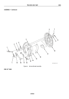
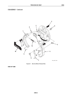
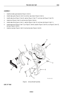
Install two brake guide washers (Figure 3, Item 3).
2.
Install brake guide (Figure 3, Item 14) and four cap screws (Figure 3, Item 4).
3.
Install brake shoe (Figure 3, Item 6), washer (Figure 3, Item 17), and new clip (Figure 3, Item 18).
4.
Install strut (Figure 3, Item 10) and new clip (Figure 3, Item 2).
5.
Install brake shoe (Figure 3, Item 1), washer (Figure 3, Item 12), and new clip (Figure 3, Item 11).
6.
Install brake lever (Figure 3, Item 7), pin (Figure 3, Item 8), washer (Figure 3, Item 16), nut (Figure 3, Item 15),
and cap (Figure 3, Item 5).
7.
Install two springs (Figure 3, Item 13) and spring clips (Figure 3, Item 9).
2
1
3
11
12
9
10
8
7
18
17
6
13
5
4
3
16
15
14
M116_M101_082
Figure 3.
Service Brake Assembly.
END OF TASK
TM 9-2330-202-13&P
0046
0046-6
Back to Top

