TM-9-2330-202-13-P - Page 234 of 552
REMOVAL
NOTE
•
Use a suitable container to catch any draining brake fluid. Make sure all spills are cleaned
up. Refer to local procedures for responding to fluid spills and disposal of clean up
materials. Refer to local procedures for storage and disposal of drained fluids.
•
If removing or replacing wheel cylinder, do Steps 1 and 2 only. If removing or replacing
bleeder valve only, do Step 3 only.
1.
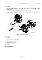
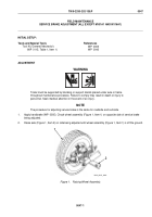
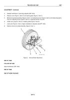
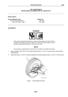
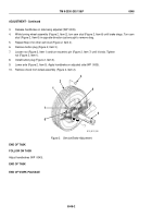
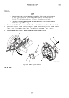
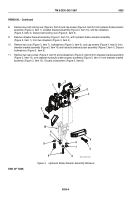
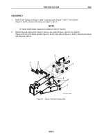
Disconnect hydraulic brake tube assembly (Figure 1, Item 1) at inlet to wheel cylinder (Figure 1, Item 6).
2.
Remove bolt (Figure 1, Item 4), lockwasher (Figure 1, Item 3), wheel cylinder (Figure 1, Item 6), and link
(Figure 1, Item 7) from backing plate (Figure 1, Item 8). Discard lockwasher (Figure 1, Item 3).
3.
Remove bleeder valve (Figure 1, Item 2) from wheel cylinder (Figure 1, Item 6).
1
6
3
7
8
1
2
5
4
M116_M101_087A
Figure 1.
Wheel Cylinder Removal.
END OF TASK
TM 9-2330-202-13&P
0049
0049-2
Back to Top

