TM-9-2330-202-13-P - Page 236 of 552
INSTALLATION
1.
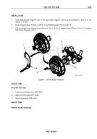
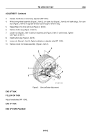
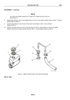
If removed, install bleeder valve (Figure 2, Item 2) on wheel cylinder (Figure 2, Item 6).
CAUTION
Make sure boot of wheel cylinder is dry before installing wheel cylinder. Failure to follow this
caution may cause brake fluid to damage brake shoe linings. Failure to comply may result in
damage to, or destruction of, equipment or mission.
2.
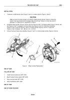
Assemble wheel cylinder (Figure 2, Item 6) and link (Figure 2, Item 7) at backing plate (Figure 2, Item 8), with
link (Figure 2, Item 7) engaged in primary brake shoe (Figure 2, Item 5). Install new lockwasher
(Figure 2, Item 3) and bolt (Figure 2, Item 4) on wheel cylinder (Figure 2, Item 6). Torque bolt
(Figure 2, Item 4) between 130 – 280 lb-in (15 – 32 N•m).
3.
Connect hydraulic brake tube assembly (Figure 2, Item 1) to inlet of wheel cylinder (Figure 2, Item 6).
1
6
3
7
8
1
2
5
4
M116_M101_087
Figure 2.
Wheel Cylinder Replacement.
END OF TASK
FOLLOW ON TASK
1.
Install hub and brake drum (WP
0055).
2.
Bleed hydraulic brake system (WP
0053).
3.
Adjust service brake (WP
0048).
4.
Adjust handbrakes (WP
0043).
END OF TASK
END OF WORK PACKAGE
TM 9-2330-202-13&P
0049
0049-4
Back to Top

