TM-9-2330-202-13-P - Page 242 of 552
DISASSEMBLY - Continued
3.
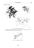
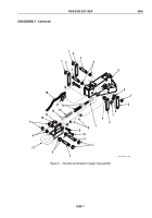
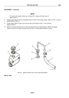
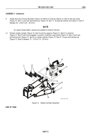
Remove eight self-locking nuts (Figure 5, Item 1), four links (Figure 5, Item 2) and shafts (Figure 5, Item 3),
eight bearings (Figure 5, Item 4), and drawbar coupler (Figure 5, Item 11) from channel (Figure 5, Item 5).
Discard self-locking nuts (Figure 5, Item 1).
4.
Remove self-locking nut (Figure 5, Item 12), cap screw (Figure 5, Item 10), and shock absorber
(Figure 5, Item 8) from drawbar coupler (Figure 5, Item 11). Discard self-locking nut (Figure 5, Item 12).
NOTE
Boot may be in master cylinder.
5.
Remove self-locking nut (Figure 5, Item 13) and socket head screw (Figure 5, Item 9) from drawbar coupler
(Figure 5, Item 11) and pushrod (Figure 5, Item 16). Remove washer (Figure 5, Item 14), spring
(Figure 5, Item 15), pushrod (Figure 5, Item 16), and boot (Figure 5, Item 7) from drawbar coupler
(Figure 5, Item 11). Discard self-locking nut (Figure 5, Item 13).
6.
Remove self-locking nut (Figure 5, Item 6), cap screw (Figure 5, Item 19), and breakaway lever
(Figure 5, Item 17), with chain (Figure 5, Item 18) from channel (Figure 5, Item 5). Discard self-locking
nut (Figure 5, Item 6).
7.
If damaged, remove chain (Figure 5, Item 18) from breakaway lever (Figure 5, Item 17).
TM 9-2330-202-13&P
0050
0050-6
Back to Top

