TM-9-2330-202-13-P - Page 251 of 552
INSTALLATION - Continued
NOTE
Bracket and adjustable front support leg is a one-piece welded assembly.
6.
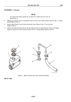
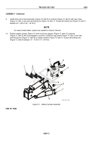
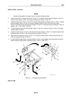
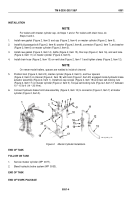
Install bracket with front support leg (Figure 14, Item 11) on drawbar bracket assembly (Figure 14, Item 12)
with cap screw (Figure 14, Item 10) and new self-locking nut (Figure 14, Item 13).
7.
Install two safety chains (Figure 14, Item 9) on hydraulic brake actuator assembly (Figure 14, Item 1), drawbar
bracket assembly (Figure 14, Item 12), and two drawbars (Figure 14, Item 15) with two cap screws
(Figure 14, Item 8) and new self-locking nuts (Figure 14, Item 14). Torque self-locking nut (Figure 14, Item 14)
between 165 – 175 lb-ft (224 – 237 N•m).
8.
Connect hydraulic brake front tube assembly (Figure 14, Item 6) to connector (Figure 14, Item 5) at master
cylinder (Figure 14, Item 4).
9.
Install loop clamp (Figure 14, Item 3), with intervehicular cable (Figure 14, Item 7) on hydraulic brake actuator
assembly (Figure 14, Item 1) with new self-locking nut (Figure 14, Item 2).
10.
Make sure front support leg (Figure 14, Item 11) is locked in lowered position. Remove lifting devices from
under two drawbars (Figure 14, Item 15).
11.
If a new hydraulic brake actuator assembly (Figure 14, Item 1) was installed, install new brake fluid caution
decal to hydraulic brake actuator assembly (Figure 14, Item 11) (WP
0007).
1
1
9
9
10
11
12
13
14
15
2
3
4
5
6
7
8
M116_M101_4-71A
Figure 14.
Front Support Leg Installation.
END OF TASK
TM 9-2330-202-13&P
0050
0050-15
Back to Top

