TM-9-2330-202-13-P - Page 260 of 552
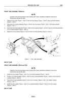
REAR TUBE ASSEMBLY INSTALLATION
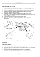
1.
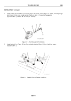
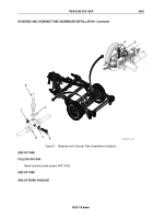
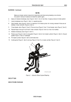
On the M101A2 and M116A2, install two loop clamps (Figure 3, Item 7) and loop clamp (Figure 3, Item 4) on
rear tube assembly (Figure 3, Item 2).
2.
Position rear tube assembly (Figure 3, Item 2) along curbside frame (Figure 3, Item 6) and crossmember.
3.
On the M101A3 and M116A3, connect rear tube assembly (Figure 3, Item 2) to hose assembly
(Figure 3, Item 1) at retaining ring (Figure 3, Item 9).
4.
On the M101A2 and M116A2, connect rear tube assembly (Figure 3, Item 2) to hose assembly
(Figure 3, Item 1). Secure loop clamp (Figure 3, Item 4) to crossmember with screw (Figure 3, Item 11) and
new self-locking nut (Figure 3, Item 3).
5.
Connect rear tube assembly (Figure 3, Item 2) to coupling (Figure 3, Item 5).
6.
Install two loop clamps (Figure 3, Item 7) on curbside frame (Figure 3, Item 6) with two screws
(Figure 3, Item 8).
11
M101A2 and M116A2
M101A3 and M116A3
1
1
1
1
2
3
4
5
6
7
8
9
10
M116_M101_4-78
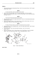
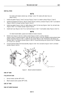
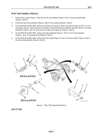
Figure 3.
Rear Tube Assembly Installation.
END OF TASK
HOSE ASSEMBLY REMOVAL
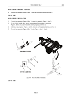
1.
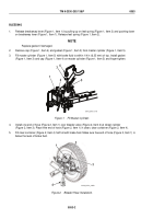
Disconnect hose assembly (Figure 4, Item 1) from tee (Figure 4, Item 4) at axle.
2.
Remove copper gasket (Figure 4, Item 3), if present, from hose assembly (Figure 4, Item 1). Discard copper
gasket (Figure 4, Item 3).
3.
On the M101A3 and M116A3, remove retaining ring (Figure 4, Item 5) from hose assembly
(Figure 4, Item 1) and release hose assembly (Figure 4, Item 1) from bracket (Figure 4, Item 6)
on crossmember.
TM 9-2330-202-13&P
0052
0052-4
Back to Top

