TM-9-2330-202-13-P - Page 262 of 552
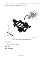
ROADSIDE AND CURBSIDE TUBE ASSEMBLIES REMOVAL
1.
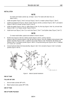
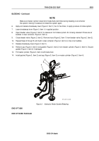
Disconnect tube assembly (Figure 5, Item 5) from wheel cylinder (Figure 5, Item 4).
2.
Disconnect tube assembly (Figure 5, Item 5) from tee (Figure 5, Item 8) and remove from axle.
NOTE
Do Steps 3 and 4 to remove tee from axle.
3.
Disconnect hose assembly (Figure 5, Item 2) from tee (Figure 5, Item 8). Remove copper gasket
(Figure 5, Item 3), if present, from hose assembly (Figure 5, Item 2). Discard copper gasket (Figure 5, Item 3)
4.
Remove cap screw (Figure 5, Item 6), washer (Figure 5, Item 7), tee (Figure 5, Item 8), and lockwasher
(Figure 5, Item 1) from axle. Discard lockwasher (Figure 5, Item 1).
END OF TASK
ROADSIDE AND CURBSIDE TUBE ASSEMBLIES INSTALLATION
NOTE
•
Do Steps 1 and 2 to install tee on axle.
•
The procedure for installing assemblies is the same for roadside and curbside.
1.
Install new lockwasher (Figure 5, Item 1), tee (Figure 5, Item 8), washer (Figure 5, Item 7), and cap screw
(Figure 5, Item 6) on axle.
2.
Install new copper gasket (Figure 5, Item 3), if present, on hose assembly (Figure 5, Item 2). Connect hose
assembly (Figure 5, Item 2) to tee (Figure 5, Item 8).
3.
Position tube assembly (Figure 5, Item 5) along axle and connect to tee (Figure 5, Item 8).
4.
Connect tube assembly (Figure 5, Item 5) to wheel cylinder (Figure 5, Item 4).
TM 9-2330-202-13&P
0052
0052-6
Back to Top

