TM-9-2330-202-13-P - Page 258 of 552
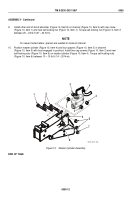
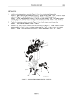
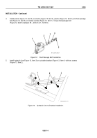
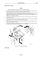
FRONT TUBE ASSEMBLY REMOVAL
NOTE
Quantity of mounting hardware varies slightly with model. Quantities indicated in task are for
the M101A3 and the M116A3.
1.
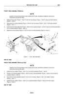
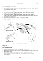
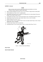
Remove five screws (Figure 1, Item 5) from five loop clamps (Figure 1, Item 3) along curbside drawbar
(Figure 1, Item 2).
2.
Disconnect front tube assembly (Figure 1, Item 4) from connector (Figure 1, Item 7) at master cylinder
(Figure 1, Item 1).
3.
Disconnect front tube assembly (Figure 1, Item 4) from coupling (Figure 1, Item 6). Remove front tube assembly
from curbside drawbar (Figure 1, Item 2).
4.
Remove five loop clamps (Figure 1, Item 3) from front tube assembly (Figure 1, Item 4).
5
6
4
4
1
2
3
4
7
M116_M101_4-76
Figure 1.
Front Tube Assembly.
END OF TASK
FRONT TUBE ASSEMBLY INSTALLATION
NOTE
Quantity of mounting hardware varies slightly with model. Quantities indicated in task are for
the M101A3 and the M116A3.
1.
Install five loop clamps (Figure 1, Item 3) on front tube assembly (Figure 1, Item 4).
2.
Position front tube assembly (Figure 1, Item 4) along curbside drawbar (Figure 1, Item 2) and connect to
coupling (Figure 1, Item 6).
3.
Connect front tube assembly (Figure 1, Item 4) to connector (Figure 1, Item 7) at master cylinder
(Figure 1, Item 1).
4.
Install five loop clamps (Figure 1, Item 3) on curbside drawbar (Figure 1, Item 2) with five screws
(Figure 1, Item 5).
END OF TASK
TM 9-2330-202-13&P
0052
0052-2
Back to Top

