TM-9-2330-202-13-P - Page 256 of 552
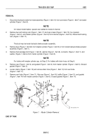
INSTALLATION
NOTE
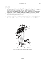
For trailers with master cylinder cap, do Steps 1 and 2. For trailers with drain hose, do
Steps 3 and 4.
1.
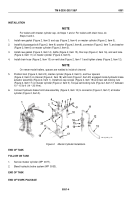
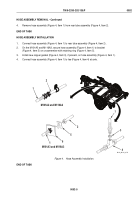
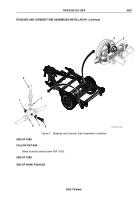
Install new gasket (Figure 2, Item 3) and cap (Figure 2, Item 4) on master cylinder (Figure 2, Item 5).
2.
Install fluid passage bolt (Figure 2, Item 9), washer (Figure 2, Item 8), connector (Figure 2, Item 7), and washer
(Figure 2, Item 6) on master cylinder (Figure 2, Item 5).
3.
Install new gasket (Figure 2, Item 14), baffle (Figure 2, Item 15), filler cap (Figure 2, Item 16), and vent tube
(Figure 2, Item 11) on master cylinder (Figure 2, Item 5).
4.
Install drain hose (Figure 2, Item 13) on vent tube (Figure 2, Item 11) and tighten clamp (Figure 2, Item 12).
NOTE
On newer-model trailers, spacers are welded to inside of channel.
5.
Position boot (Figure 2, Item 20), master cylinder (Figure 2, Item 5), and four spacers
(Figure 2, Item 2) in channel (Figure 2, Item 18) with boot (Figure 2, Item 20) engaged inside hydraulic brake
actuator assembly (Figure 2, Item 1). Install two cap screws (Figure 2, Item 19) and new self-locking nuts
(Figure 2, Item 17) on master cylinder (Figure 2, Item 5). Torque self-locking nuts (Figure 2, Item 17) between
10 – 15 lb-ft (14 – 20 N•m).
6.
Connect hydraulic brake front tube assembly (Figure 2, Item 10) to connector (Figure 2, Item 7) at master
cylinder (Figure 2, Item 5).
1
2
2
3
4
5
6
7
8
9
10
11
12
13
14
15
16
17
18
19
20
M116_M101_4-74
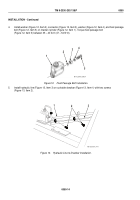
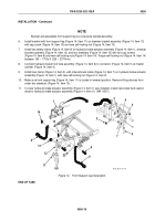
Figure 2.
Master Cylinder Installation.
END OF TASK
FOLLOW ON TASK
1.
Service master cylinder (WP
0077).
2.
Bleed hydraulic brake system (WP
0053).
END OF TASK
END OF WORK PACKAGE
TM 9-2330-202-13&P
0051
0051-4
Back to Top

