TM-9-2330-202-13-P - Page 261 of 552
HOSE ASSEMBLY REMOVAL - Continued
4.
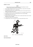
Remove hose assembly (Figure 4, Item 1) from rear tube assembly (Figure 4, Item 2).
END OF TASK
HOSE ASSEMBLY INSTALLATION
1.
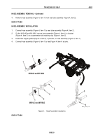
Connect hose assembly (Figure 4, Item 1) to rear tube assembly (Figure 4, Item 2).
2.
On the M101A3 and M116A3, secure hose assembly (Figure 4, Item 1) to bracket
(Figure 4, Item 5) on crossmember with retaining ring (Figure 4, Item 5).
3.
Install new copper gasket (Figure 4, Item 3), if present, on hose assembly (Figure 4, Item 1).
4.
Connect hose assembly (Figure 4, Item 1) to tee (Figure 4, Item 4) at axle.
M101A2 and M116A2
M101A3 and M116A3
1
1
2
2
3
4
5
6
1
M116_M101_4-79
Figure 4.
Hose Assembly Installation.
END OF TASK
TM 9-2330-202-13&P
0052
0052-5
Back to Top

