TM-9-2330-202-13-P - Page 248 of 552
ASSEMBLY - Continued
9.
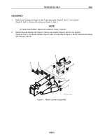
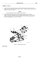
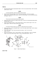
Install other end of shock absorber (Figure 10, Item 8) on channel (Figure 10, Item 5) with cap screw
(Figure 10, Item 1) and new self-locking nut (Figure 10, Item 7). Torque self-locking nut (Figure 10, Item 7)
between 20 – 25 lb-ft (27 – 34 N•m).
NOTE
On newer-model trailers, spacers are welded to inside of channel.
10.
Position master cylinder (Figure 10, Item 4) and four spacers (Figure 10, Item 3) in channel
(Figure 10, Item 5) with boot engaged in pushrod. Install two cap screws (Figure 10, Item 2) and new
self-locking nuts (Figure 10, Item 6) on master cylinder (Figure 10, Item 4). Torque self-locking nuts
(Figure 10, Item 6) between 10 – 15 lb-ft (14 – 20 N•m).
1
2
3
3
4
5
6
7
3
3
8
M116_M101_096
Figure 10.
Master Cylinder Assembly.
END OF TASK
TM 9-2330-202-13&P
0050
0050-12
Back to Top

