TM-9-2330-202-13-P - Page 238 of 552
REMOVAL
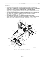
1.
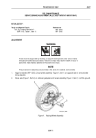
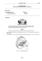
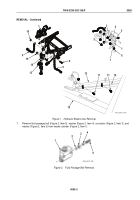
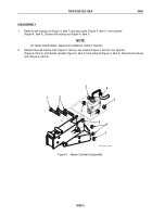
Place lifting device under drawbar (Figure 1, Item 12) at each front corner of frame.
WARNING
Accidental or intentional introduction of liquid contaminants into the environment is a violation
of state, federal, and military regulations. Refer to local environmental office for information
concerning storage, use, and disposal of these liquids. Failure to comply may cause damage
to environment and health of personnel. Seek medical attention in the event of an injury.
NOTE
Use a suitable container to catch any draining brake fluid. Make sure all spills are cleaned
up. Refer to local procedures for responding to fluid spills and disposal of clean up materials.
Refer to local procedures for storage and disposal of drained fluids.
2.
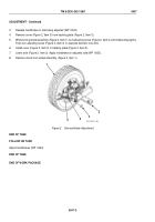
Remove self-locking nut (Figure 1, Item 2) and loop clamp (Figure 1, Item 3), with intervehicular cable
(Figure 1, Item 7) from hydraulic brake actuator assembly (Figure 1, Item 1). Discard self-locking nut
(Figure 1, Item 2).
3.
Disconnect hydraulic brake front tube assembly (Figure 1, Item 6) from connector (Figure 1, Item 5) at master
cylinder (Figure 1, Item 4).
4.
Remove self-locking nut (Figure 1, Item 16), cap screw (Figure 1, Item 8), and safety chain (Figure 1, Item 9)
from each of two drawbars (Figure 1, Item 12). Discard self-locking nuts (Figure 1, Item 16).
NOTE
Bracket and adjustable front support leg is a one-piece welded assembly.
5.
Remove self-locking nut (Figure 1, Item 15), cap screw (Figure 1, Item 17), and bracket with front support leg
(Figure 1, Item 13) drawbar bracket assembly (Figure 1, Item 14). Discard self-locking nut (Figure 1, Item 15).
6.
Remove two screws (Figure 1, Item 11) and loosen hydraulic line (Figure 1, Item 10) from curbside drawbar
(Figure 1, Item 12).
TM 9-2330-202-13&P
0050
0050-2
Back to Top


