TM-9-2330-202-13-P - Page 240 of 552
REMOVAL - Continued
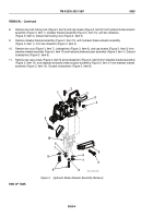
8.
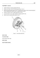
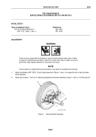
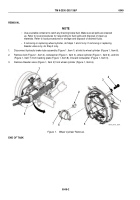
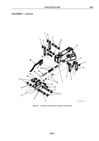
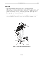
Remove four self-locking nuts (Figure 3, Item 3) and cap screws (Figure 4, Item 5) from hydraulic brake actuator
assembly (Figure 3, Item 1), drawbar bracket assembly (Figure 3, Item 10), and two drawbars
(Figure 3, Item 4). Discard self-locking nuts (Figure 3, Item 3).
9.
Remove drawbar bracket assembly (Figure 3, Item 10), with hydraulic brake actuator assembly
(Figure 3, Item 1), from two drawbars (Figure 3, Item 4).
10.
Remove two nuts (Figure 3, Item 7), lockwashers (Figure 3, Item 6), and cap screws (Figure 3, Item 2) from
drawbar bracket assembly (Figure 3, Item 10) and hydraulic brake actuator assembly (Figure 3, Item 1). Discard
lockwashers (Figure 3, Item 6).
11.
Remove two cap screws (Figure 3, Item 9) and lockwashers (Figure 3, Item 8) from drawbar bracket assembly
(Figure 3, Item 10), and separate hydraulic brake actuator assembly (Figure 3, Item 1) from drawbar bracket
assembly (Figure 3, Item 10). Discard lockwashers (Figure 3, Item 8).
5
1
2
2
3
3
4
5
6
6
7
7
8
8
9
10
M116_M101_097
Figure 3.
Hydraulic Brake Actuator Assembly Removal.
END OF TASK
TM 9-2330-202-13&P
0050
0050-4
Back to Top

