TM-9-2330-202-13-P - Page 193 of 552
FIELD MAINTENANCE
INTERVEHICULAR CABLE REPLACEMENT
INITIAL SETUP:
Tools and Special Tools
Tool Kit, General Mechanic's
(WP
0115, Table 1, Item 1)
Materials/Parts
Seven lockwashers (WP
0085, Figure 4, Item 2)
Self-locking nut (WP
0091, Figure 10, Item 13)
Tag, marker (as needed)
(WP
0114, Table 1, Item 25)
Equipment Condition
Intervehicular cable disconnected from
prime mover (WP
0005)
NOTE
Configuration of intervehicular cable and mounting varies slightly with model.
REMOVAL
1.
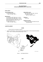
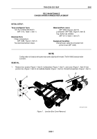
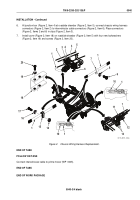
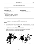
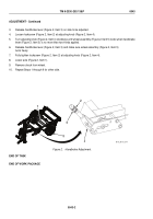
Remove four screws (Figure 1, Item 1) and lockwashers (Figure 1, Item 2) and cover (Figure 1, Item 3) from
junction box (Figure 1, Item 8) at roadside drawbar (Figure 1, Item 4). Discard lockwashers (Figure 1, Item 2).
NOTE
If marker bands are missing or illegible, tag wires for installation.
2.
At junction box (Figure 1, Item 8) at roadside drawbar (Figure 1, Item 4), remove chassis wiring harness
connectors (Figure 1, Item 7) and intervehicular cable connectors (Figure 1, Item 6) from clips
(Figure 1, Item 5) and disconnect connectors (Figure 1, Items 6 and 7).
4
8
7
2
1
3
5
6
4
M116_M101_065
Figure 1.
Intervehicular Cable Junction Box Connections Removal.
TM 9-2330-202-13&P
0041
0041-1
Back to Top

