TM-9-2330-202-13-P - Page 187 of 552
CLEANING AND INSPECTION
1.
Use detergent and water to clean housing. Dry thoroughly.
2.
Use abrasive cloth to remove corrosion from lens retainer and housing.
3.
Touch up paint, refer to TM 43-0139.
4.
Inspect lens retainer for signs of moisture leakage, cracks, warpage, and damaged screwdriver slots or threads
on screws, Inspect lenses for cracks or breaks. Replace lens retainer if lens retainer or lenses are damaged.
5.
Inspect housing for cracks and dents. Replace housing if damaged.
6.
Inspect grommet for damage. Inspect retaining plate for cracks and distortion. Inspect socket and wiring
assembly for good electrical and mechanical connections, cracked or bad insulation, broken wires, corroded
sockets or terminals, and cracked isolators. Replace socket and wiring assembly, retaining plate, and grommet
as an assembly if grommet, retaining plate, or socket and wiring assembly is damaged.
END OF TASK
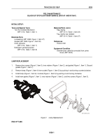
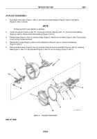
STOPLIGHT ASSEMBLY
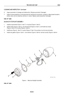
1.
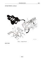
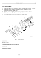
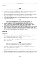
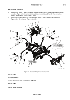
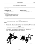
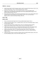
Slip wires through hole in housing (Figure 4, Item 1).
2.
Position grommet (Figure 4, Item 15), retaining plate (Figure 4, Item 14), and socket and wiring assembly
(Figure 4, Item 4) inside housing (Figure 4, Item 1) with double socket at top. Install three screws
(Figure 4, Item 13).
3.
Install two new lockwashers (Figure 4, Item 5) and screws (Figure 4, Item 6).
4.
Install lamp (Figure 4, Item 8) in top-left socket (Figure 4, Item 7) and lamp (Figure 4, Item 8) in bottom socket
(Figure 4, Item 7) by pushing in and turning clockwise.
5.
Install lamp (Figure 4, Item 12) in top-right socket (Figure 4, Item 7) by pushing in and turning clockwise.
6.
Slip three shells (Figure 4, Item 2) over electrical contacts and wires. Install three slotted washers
(Figure 4, Item 3) in back of electrical contacts and pull shells (Figure 4, Item 2) over slotted washers
(Figure 4, Item 3) and electrical contacts.
END OF TASK
TM 9-2330-202-13&P
0039
0039-5
Back to Top

