TM-9-2330-202-13-P - Page 190 of 552
REMOVAL - Continued
NOTE
If marker bands are missing or illegible, tag wires for installation.
2.
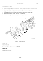
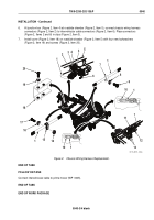
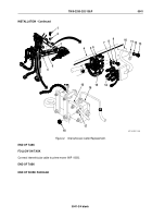
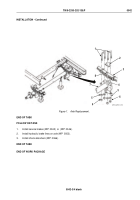
At junction box (Figure 2, Item 4) at roadside drawbar (Figure 2, Item 5), remove chassis wiring harness
connectors (Figure 2, Item 2) and intervehicular cable connectors (Figure 2, Item 6) from clips
(Figure 2, Item 3) and disconnect connectors (Figure 2, Items 2 and 6).
3.
At curbside and roadside rear of trailer, remove chassis wiring harness connectors (Figure 2, Item 12) and
light connectors (Figure 2, Item 13) from clips (Figure 2, Item 11) and disconnect connectors
(Figure 2, Items 12 and 13).
4.
Remove electrical tiedown straps (Figure 2, Item 10) from chassis wiring harness (Figure 2, Item 1). Discard
tiedown straps (Figure 2, Item 10).
NOTE
The M116A3 has no lockwashers at loop clamp mountings on rear crossmember and
roadside frame. A lockwasher is used at loop clamp mounting on roadside drawbar.
5.
Remove 11 screws (Figure 2, Item 9) and lockwashers (Figure 2, Item 8) from 11 loop clamps
(Figure 2, Item 7) securing chassis wiring harness (Figure 2, Item 1) to rear crossmember, roadside
frame, and roadside drawbar (Figure 2, Item 5). Discard lockwashers (Figure 2, Item 8).
6.
At front roadside corner of frame, remove nut (Figure 2, Item 14), screw (Figure 2, Item 17), and lockwasher
(Figure 2, Item 16) from loop clamp (Figure 2, Item 15) and frame. Discard lockwasher (Figure 2, Item 16).
7.
Remove chassis wiring harness (Figure 2, Item 1) from frame. Remove 11 loop clamps (Figure 2, Item 7) and
loop clamp (Figure 2, Item 15) from chassis wiring harness (Figure 2, Item 1).
END OF TASK
INSTALLATION
1.
Place 11 loop clamps (Figure 2, Item 7) and loop clamp (Figure 2, Item 15) on chassis wiring harness
(Figure 2, Item 1). Position chassis wiring harness (Figure 2, Item 1) along rear crossmember, roadside frame,
and roadside drawbar (Figure 2, Item 5). Make sure chassis wiring harness connectors
(Figure 2, Items 2 and 12) reach their points of connection.
2.
At front roadside corner of frame, install loop clamp (Figure 2, Item 15) on frame with new lockwasher
(Figure 2, Item 16), screw (Figure 2, Item 17), and nut (Figure 2, Item 14) securing chassis wiring harness
(Figure 2, Item 1) to frame.
NOTE
The M116A3 has no lockwashers at loop clamp mountings on rear crossmember and
roadside frame. A lockwasher is used at loop clamp mounting on roadside drawbar.
3.
Install 11 loop clamps (Figure 2, Item 7) securing chassis wiring harness (Figure 2, Item 1) to rear
crossmember, roadside frame, and roadside drawbar (Figure 2, Item 5) with 11 new lockwashers
(Figure 2, Item 8) and screws (Figure 2, Item 9).
4.
Loop excess chassis wiring harness (Figure 2, Item 1) and secure with new electrical tiedown straps
(Figure 2, Item 10).
5.
At curbside and roadside rear of trailer, connect chassis wiring harness connectors (Figure 2, Item 12) to light
connectors (Figure 2, Item 13). Place connectors (Figure 2, Items 12 and 13) in clips (Figure 2, Item 11).
TM 9-2330-202-13&P
0040
0040-2
Back to Top

