TM-9-2330-202-13-P - Page 194 of 552
REMOVAL - Continued
3.
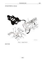
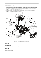
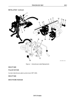
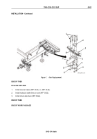
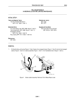
Remove screw (Figure 2, Item 9), lockwasher (Figure 2, Item 8), and ground terminal (Figure 2, Item 7) from
roadside drawbar (Figure 2, Item 4). Discard lockwasher (Figure 2, Item 8).
4.
Remove two screws (Figure 2, Item 13) and lockwashers (Figure 2, Item 12) and retaining strap
(Figure 2, Item 11) from intervehicular cable (Figure 2, Item 10) and roadside drawbar (Figure 2, Item 4).
Discard lockwashers (Figure 2, Item 12).
5.
Remove self-locking nut (Figure 2, Item 18) and loop clamp (Figure 2, Item 17) from hydraulic brake actuator
assembly (Figure 2, Item 16). Remove loop clamp (Figure 2, Item 17) from intervehicular cable
(Figure 2, Item 10). Discard self-locking nut (Figure 2, Item 18).
END OF TASK
INSTALLATION
1.
Position intervehicular cable (Figure 2, Item 10) along roadside drawbar (Figure 2, Item 4).
2.
Install ground terminal (Figure 2, Item 7) on drawbar (Figure 2, Item 4) with new lockwasher (Figure 2, Item 8)
and screw (Figure 2, Item 9).
3.
Connect chassis wiring harness connectors (Figure 2, Item 15) to intervehicular cable connectors
(Figure 2, Item 14). Place connectors (Figure 2, Items 14 and 15) in clips (Figure 2, Item 5).
4.
Install retaining strap (Figure 2, Item 11) on intervehicular cable (Figure 2, Item 10) and roadside drawbar
(Figure 2, Item 4) with two new lockwashers (Figure 2, Item 12) and screws (Figure 2, Item 13).
5.
Install loop clamp (Figure 2, Item 17) on intervehicular cable (Figure 2, Item 10). Install loop clamp
(Figure 2, Item 17) on hydraulic brake actuator assembly (Figure 2, Item 16) with new self-locking nut
(Figure 2, Item 18).
6.
Install cover (Figure 2, Item 3) on junction box (Figure 2, Item 6) at roadside drawbar (Figure 2, Item 4) with
four new lockwashers (Figure 2, Item 2) and screws (Figure 2, Item 1).
TM 9-2330-202-13&P
0041
0041-2
Back to Top

