TM-9-2330-202-13-P - Page 328 of 552
REMOVAL - Continued
3.
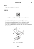
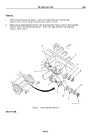
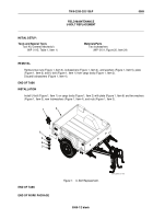
At each of two rear corner mounting brackets (Figure 2, Item 13), remove two self-locking nuts
(Figure 2, Item 14) and cap screws (Figure 2, Item 12) from mounting bracket (Figure 2, Item 13). Discard
self-locking nuts (Figure 2, Item 14).
4.
At rear chassis sill, remove self-locking nut (Figure 2, Item 10) and cap screw (Figure 2, Item 11) from cargo
body (Figure 2, Item 3) and frame (Figure 2, Item 5). Discard self-locking nut (Figure 2, Item 10).
5.
At each of two midchassis mounting brackets (Figure 2, Item 1), remove self-locking nut (Figure 2, Item 15)
and cap screw (Figure 2, Item 2) from mounting brackets (Figure 2, Item 1). Discard self-locking nuts
(Figure 2, Item 15).
6.
At front chassis sill, remove three self-locking nuts (Figure 2, Item 6) and cap screws (Figure 2, Item 4) from
cargo body (Figure 2, Item 3) and frame (Figure 2, Item 5). Discard self-locking nuts (Figure 2, Item 6).
WARNING
Two personnel are required to help guide the cargo body to and from frame. Failure to comply
may result in death or injury to personnel. Seek medical attention in the event of an injury.
7.
Lift cargo body (Figure 2, Item 3) from frame (Figure 2, Item 5) with lifting device and secure. Remove lifting
device from cargo body (Figure 2, Item 3).
END OF TASK
INSTALLATION
1.
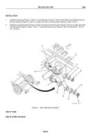
Attach a suitable lifting device to cargo body (Figure 2, Item 3).
WARNING
Two personnel are required to help guide the cargo body to and from frame. Failure to comply
may result in death or injury to personnel. Seek medical attention in the event of an injury.
2.
Lift cargo body (Figure 2, Item 3) onto frame (Figure 2, Item 5) and align mounting holes.
3.
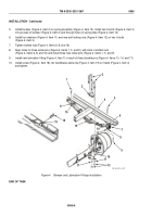
At front chassis sill, loosely install three cap screws (Figure 2, Item 4) and new self-locking nuts
(Figure 2, Item 6) on cargo body (Figure 2, Item 3) and frame (Figure 2, Item 5).
4.
At each of two midchassis mounting brackets (Figure 2, Item 1), loosely install cap screw (Figure 2, Item 2)
and new self-locking nut (Figure 2, Item 15) on mounting brackets (Figure 2, Item 1).
5.
At rear chassis sill, loosely install cap screw (Figure 2, Item 11) and new self-locking nut (Figure 2, Item 10)
on cargo body (Figure 2, Item 3) and frame (Figure 2, Item 5).
6.
At each of two rear corner mounting brackets (Figure 2, Item 13), loosely install two cap screws
(Figure 2, Item 12) and new self-locking nuts (Figure 2, Item 14) on mounting brackets (Figure 2, Item 13).
TM 9-2330-202-13&P
0067
0067-2
Back to Top

