TM-9-2330-202-13-P - Page 320 of 552
INSTALLATION - Continued
5.
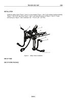
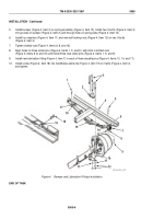
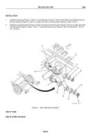
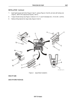
Install bumper (Figure 4, Item 2) on spring assembly (Figure 4, Item 15). Install two U-bolts (Figure 4, Item 3)
into grooves of bumper (Figure 4, Item 2) and through holes in spring plate (Figure 4, Item 10).
6.
Install four washers (Figure 4, Item 11) and new self-locking nuts (Figure 4, Item 12) on two U-bolts
(Figure 4, Item 3).
7.
Tighten slotted nuts (Figure 4, Items 6, 8, and 16).
8.
Align holes for three cotter pins (Figure 4, Items 1, 5, and 9 ) with slots in slotted nuts
(Figure 4, Items 6, 8, and 16) and install three new cotter pins (Figure 4, Items 1, 5, and 9).
9.
Install new lubrication fitting (Figure 4, Item 7) in each of three shackle pins (Figure 4, Items 13, 14, and 17).
10.
Install screw (Figure 4, Item 18) into handbrake cable clip (Figure 4, Item 19) on frame (Figure 4, Item 4)
and tighten.
1
2
3
4
5
6
7
8
9
10
11
12
13
14
15
16
17
18
19
11
M116_M101_4-107
Figure 4.
Bumper and Lubrication Fittings Installation.
END OF TASK
TM 9-2330-202-13&P
0065
0065-6
Back to Top

