TM-9-2330-202-13-P - Page 316 of 552
REMOVAL
1.
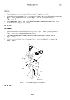
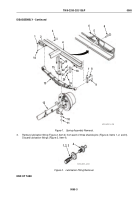
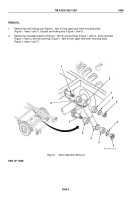
Place lifting device under axle (Figure 1, Item 12), raise trailer, and place suitable support at rear of trailer.
2.
Lower axle (Figure 1, Item 12) until weight of trailer rests on support at rear of trailer. Some weight will be on
lifting device.
3.
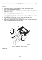
Remove four self-locking nuts (Figure 1, Item 11) and washers (Figure 1, Item 10), two U-bolts
(Figure 1, Item 16), and bumper (Figure 1, Item 15) from axle (Figure 1, Item 12) and spring assembly
(Figure 1, Item 13). Discard self-locking nuts (Figure 1, Item 11).
4.
Remove screw (Figure 1, Item 6) from handbrake cable clip (Figure 1, Item 5) on frame (Figure 1, Item 4).
5.
Lower axle (Figure 1, Item 12) approximately 4 inches (10 cm) to take weight off spring assembly
(Figure 1, Item 13).
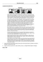
WARNING
Spring weighs over 100 lb (45 kg). Use suitable lifting device. Failure to comply may result in
death or injury to personnel. Seek medical attention in the event of an injury.
6.
At rear spring hanger (Figure 1, Item 17), remove cotter pin (Figure 1, Item 19), slotted nut (Figure 1, Item 20),
and shackle pin (Figure 1, Item 9) from two shackles (Figure 1, Items 7 and 18) and, with the aid of an assistant,
remove spring assembly (Figure 1, Item 13). Discard cotter pin (Figure 1, Item 19).
7.
At front spring hanger (Figure 1, Item 2), remove cotter pin (Figure 1, Item 1), slotted nut (Figure 1, Item 14),
and shackle pin (Figure 1, Item 3) from front spring hanger (Figure 1, Item 2) and spring assembly
(Figure 1, Item 13). Discard cotter pin (Figure 1, Item 1).
8.
Remove spring assembly (Figure 1, Item 13) from frame (Figure 1, Item 4).
END OF TASK
DISASSEMBLY
NOTE
Shackle pin should fit in rear spring hanger with slight resistance.
1.
At rear spring hanger (Figure 1, Item 17), check play between shackle pin (Figure 1, Item 8) and rear spring
hanger (Figure 1, Item 17). Looseness indicates a damaged shackle pin (Figure 1, Item 8) inside rear spring
hanger (Figure 1, Item 17).
2.
Remove cotter pin (Figure 1, Item 22), slotted nut (Figure 1, Item 21), shackle pin (Figure 1, Item 8), and two
shackles (Figure 1, Items 7 and 18) from rear spring hanger (Figure 1, Item 17). Discard cotter pin
(Figure 1, Item 22).
TM 9-2330-202-13&P
0065
0065-2
Back to Top

