TM-9-2330-202-13-P - Page 308 of 552
INSTALLATION
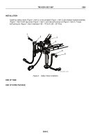
1.
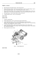
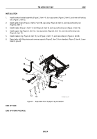
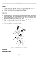
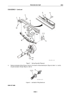
Install drawbar bracket assembly (Figure 2, Item 14), four cap screws (Figure 2, Item 5), and new self-locking
nuts (Figure 2, Item 2).
2.
Install safety chains (Figure 2, Items 7 and 18), cap screw (Figure 2, Item 6), and new self-locking nut
(Figure 2, Item 1).
3.
Install bracket (Figure 2, Item 11), bolt (Figure 2, Item 9), and new self-locking nut (Figure 2, Item 16).
4.
Install support leg (Figure 2, Item 12), two cap screws (Figure 2, Item 13), and new self-locking nuts
(Figure 2, Item 10).
5.
Install drawbar ring (Figure 2, Item 15), nut (Figure 2, Item 17), and new cotter pin (Figure 2, Item 8).
6.
Raise trailer with lifting device and remove supports (Figure 2, Item 3) from drawbars (Figure 2, Item 4). Lower
trailer to ground.
1
2
3
4
4
5
6
8
3
7
9
10
11
12
13
14
15
16
17
18
M116_M101_134
Figure 2.
Adjustable Front Support Leg Installation.
END OF TASK
END OF WORK PACKAGE
TM 9-2330-202-13&P
0062
0062-4
Back to Top


