TM-9-2330-202-13-P - Page 312 of 552
ASSEMBLY
1.
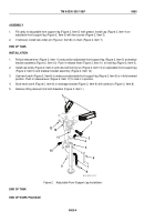
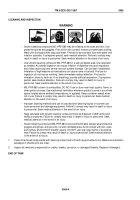
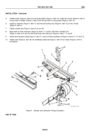
Fill cavity of adjustable front support leg (Figure 2, Item 5) with grease. Install cap (Figure 2, Item 4) on
adjustable front support leg (Figure 2, Item 5) with two screws (Figure 2, Item 3).
2.
If removed, install new cotter pin (Figure 2, Item 8) on chain (Figure 2, Item 7).
END OF TASK
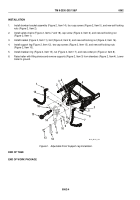
INSTALLATION
1.
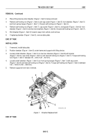
Pullout release lever (Figure 2, Item 11) and position adjustable front support leg (Figure 2, Item 5) at drawbar
bracket assembly (Figure 2, Item 12). Push in release lever (Figure 2, Item 11) to hold leg (Figure 2, Item 5).
2.
Install cap screw (Figure 2, Item 2) and new self-locking nut (Figure 2, Item 13) on adjustable front support leg
(Figure 2, Item 5) and drawbar bracket assembly (Figure 2, Item 12).
3.
Use hand crank (Figure 2, Item 6) to make sure adjustable front support leg (Figure 2, Item 5) is in fully lowered
position. Push in release lever (Figure 2, Item 11) to lock it in position.
4.
Stow hand crank (Figure 2, Item 6) on stowage bracket (Figure 2, Item 9) with cotter pin (Figure 2, Item 8).
5.
Remove lifting devices from both drawbars (Figure 2, Item 1).
1
2
3
4
5
6
7
8
9
10
11
12
13
M116_M101_4-101
Figure 2.
Adjustable Front Support Leg Installation.
END OF TASK
END OF WORK PACKAGE
TM 9-2330-202-13&P
0063
0063-4
Back to Top

