TM-9-2330-202-13-P - Page 302 of 552
REMOVAL - Continued
2.
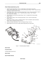
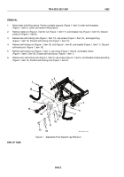
Place lifting device under drawbar (Figure 1, Item 5) being removed.
3.
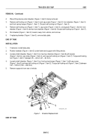
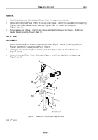
Remove self-locking nut (Figure 1, Item 2) and cap screw (Figure 1, Item 3) from drawbar (Figure 1, Item 5)
and front spring hanger (Figure 1, Item 1). Discard self-locking nut (Figure 1, Item 2).
4.
Remove self-locking nut (Figure 1, Item 7), cap screw (Figure 1, Item 4), and spacer (Figure 1, Item 6) from
drawbar (Figure 1, Item 5) and two tow shackles (Figure 1, Item 8). Discard self-locking nut (Figure 1, Item 7).
5.
Pull drawbar (Figure 1, Item 5) forward, away from vehicle, and remove.
6.
If replacing drawbar (Figure 1, Item 5), remove data plate.
END OF TASK
INSTALLATION
1.
If removed, install data plate.
2.
Position drawbar (Figure 1, Item 5) under frame and support with lifting device.
3.
Loosely install drawbar (Figure 1, Item 5) on two tow shackles (Figure 1, Item 8) with spacer
(Figure 1, Item 6), cap screw (Figure 1, Item 4), and new self-locking nut (Figure 1, Item 7). Torque self-locking
nut (Figure 1, Item 7) between 35 – 40 lb-ft (47 – 54 N•m).
4.
Loosely install drawbar (Figure 1, Item 5) on front spring hanger (Figure 1, Item 1) with cap screw
(Figure 1, Item 3) and new self-locking nut (Figure 1, Item 2). Torque self-locking nut (Figure 1, Item 2) between
140 – 150 lb-ft (190 – 203 N•m).
5.
Remove supports from rear of vehicle.
Back to Top

