TM-9-2330-247-14-P - Page 128 of 320
TM 9-2330-247-14&P
4-37.
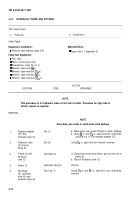
HYDRAULIC TUBES AND FlTTINGS
This Task Covers:
a.
Removal
b. Installation
Initial Setup:
Equipment Conditions:
Materials/Parts:
l Pressure tank drained (para 3-9).
l Rags (Item 11, Appendix E)
Tools/Test Equipment:
l Pan, drain
l Pliers, round-nose, long
l Screwdriver, cross-tip, no. 2
l Wrench, open-end,
~ in.
. Wrench, open-end box, ~~ in.
. Wrench, open-end box, % in.
l Wrench, open-end box, 1X6 in.
ACTION
LOCATION
ITEM
REMARKS
NOTE
This procedure Is for hydraulic tubes on left side of trailer. Procedure for right side is
similar; repeat as required.
REMOVAL
NOTE
Have drain pan ready to catch brake fluid spillage.
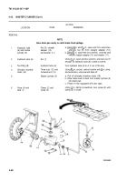
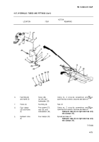
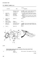
1.
Straight adapter
(27) and
hydraulic tube (2)
2.
Hydraulic tube
(2) and tee
fitting (6)
3.
Frame (3) and
hydraulic
tube (2)
4.
Frame (3)
5.
Tee fitting
(6), hydraulic
tube (9), and
hydraulic tube (8)
Nut (1)
a. Place drain pan under fittings to catch spillage.
b. Using
~ in. and fie in. open-end box wrenches,
unscrew nut (1) from straight adapter (27).
Nut (5)
Using XG in. open-end box wrench, unscrew.
Grommet (4)
a. Using long round-nose pliers, pull up and out of
frame (3).
b. Slip off hydraulic tube (2).
Hydraulic tube (2)
Pull out.
Two nuts (7)
Using X6 in. and % in. open-end box wrenches,
unscrew.
4-74
Back to Top

