TM-9-2330-335-14-P - Page 317 of 640
0068-3
TM 9-2330-335-14&P
0068
INSTALLATION AND TORQUING
00068
1.
Matching Nuts.
Matching nuts require a minimum height equal to the basic diameter of the bolt. The same is
true of tapped holes. In tapped softer materials, the depth of the tapped hole should be 1-1/2 times the basic
diameter of the bolt.
2.
Threaded Protrusion.
In all installations, bolts, studs, and screws must extend through the nut at least a length equivalent
to two complete threads. This applies to both self-locking and plain nuts.
3.
Torquing Self-Locking Nuts.
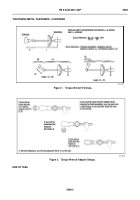
To obtain the correct recommended torque value on self-locking nuts, the nut must be
tightened until it is one turn from the beginning of seating. At this point, if the torque is less than 1/3 of the
recommended torque, it should be disregarded and the nut tightened to the recommended torque value. If the torque is
1/3 or more of the recommended torque, it should be added to the recommended torque. Example: The recommended
torque is 50 to 70 lb-in. (6 to 8 Nm). The torque at one turn from seating is 30 lb-in. (3 Nm). The correct torque wrench
reading would be 80 to 100 lb-in. (9 to 11 Nm).
4.
Retorquing Fasteners.
Procedures intended for installing metal fasteners can cause incorrect reading when used to check
or retorque already installed fasteners during maintenance. Before checking or retorquing an already installed threaded
fastener, first mark the fastener and its companion components so the marks are in line. Second, back it off a 1/4 turn to
loosen it. Torque it to the specification with an even steady pull on the torque wrench. The marks should be in line; if not,
the marks will indicate the fastener was under- or over-torqued.
5.
Standard Torque Charts.
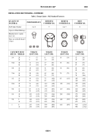
Standard torque charts have been established for dry and wet torque conditions. Surface
variations such as thread roughness, scale paint, lubrication (oil, grease, etc.), hardening, and plating may alter these
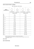
values considerably. Tables 2 and 3 are standard torque charts.
6.
To find the grade of the screw that is to be installed, match the markings on the head to the correct picture of CAPSCREW
HEAD MARKINGS on tables 2 and 3. Manufacturer’s marks may vary.
Back to Top

