TM-9-2330-342-23-P - Page 520 of 1348
MAIN HARNESS REPLACEMENT - Continued
13
1
2
3
4
5
6
7
8
9
10
11
12
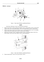
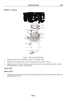
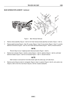
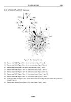
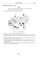
Figure 1.
Main Harness Removal.
2.
Remove diode assembly (Figure 1, Item 3) from main harness diode assembly connector (Figure 1, Item 4).
3.
Remove eight locknuts (Figure 1, Item 13), screws (Figure 1, Item 10), two chains (Figure 1, Item 11), and two
electrical connectors (Figure 1, Item 12) from trailer electrical bracket (Figure 1, Item 9). Discard locknuts.
NOTE
Perform Step (4) only if replacing trailer electrical bracket (Figure 1, Item 9).
4.
Remove four locknuts (Figure 1, Item 8), screws (Figure 1, Item 5), washers (Figure 1, Item 6), and trailer
electrical bracket (Figure 1, Item 9) from bracket (Figure 1, Item 7). Discard locknuts.
NOTE
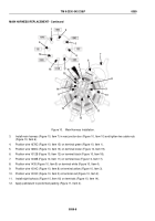
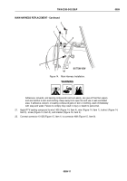
Main harness is removed from front/side marker lights the same way. Left side shown.
5.
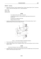
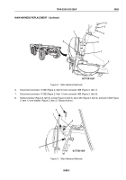
Remove screw (Figure 2, Item 2), lockwasher (Figure 2, Item 3), washer (Figure 2, Item 4), and cushion clip
(Figure 2, Item 5) from ISO lock mount (Figure 2, Item 8). Discard lockwasher.
TM 9-2330-342-23&P
0059
0059-2
Back to Top

