TM-9-2330-342-23-P - Page 609 of 1348
ADJUST - Continued
2
3
4
5
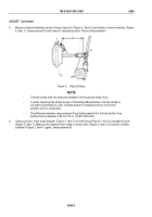
D MINUS C MUST NOT
EXCEED 2 IN. (51mm)
D
C
1
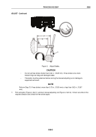
Figure 5.
Adjust Brakes.
12.
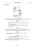
With the aid of an assistant, apply brakes while measuring distance from center of large clevis pin (Figure 5,
Item 2) to bottom of brake chamber (Figure 5, Item 1) (measurement D).
CAUTION
•
The adjusted stroke must not exceed 2 in. (51 mm), or damage to the brakes may
result.
•
The adjusted stroke should be as short as possible, but not so short that the free
stroke is less than 5/8 in. (16 mm).
•
The button must be pulled out before turning the manual adjusting nut or damage to
equipment will result.
NOTE
The difference between the measurements D and C is the adjusted chamber stroke.
13.
Pull out button (Figure 5, Item 4) and turn manual adjusting nut (Figure 5, Item 5) on slack adjuster (Figure 5,
Item 3) to adjust the brake. The adjusted stroke length must not exceed 2.0 in. (50.8 mm).
CAUTION
The button must be pulled out before turning the manual adjusting nut or damage to
equipment will result.
NOTE
•
Pull out button and turn adjusting nut counterclockwise to shorten adjusted stroke
and clockwise to lengthen adjusted stroke.
•
Perform Step (14) only if stroke length exceeds 2 in. (51 mm).
14.
Pull out button (Figure 6, Item 2) and turn manual adjusting nut (Figure 6, Item 1) 1/8 turn at a time in the
required direction and check the adjusted stroke again.
TM 9-2330-342-23&P
0066
0066-5
Back to Top

