TM-9-2330-342-23-P - Page 605 of 1348
FIELD MAINTENANCE
ADJUST BRAKES
INITIAL SETUP:
Tools and Special Tools
Socket Set, 3/8 In. (WP
0194, Table 1, Item 36)
Tool Kit, General Mechanic's: Automotive
(WP
0194, Table 1, Item 47)
Wrench, Torque, Click, Ratcheting, 3/8" Drive, 75
ft-lb (WP
0194, Table 1, Item 42)
Personnel Required
Wheeled Vehicle Mechanic (2)
Equipment Condition
Wheels chocked (TM 9-2330-342-10). (WP
0190)
Air system drained (TM 9-2330-342-10).
(WP
0190)
ADJUST
CAUTION
Button must be pulled out before turning the manual adjusting nut, or damage to equipment
will result.
NOTE
This procedure must be performed for each brake.
1.
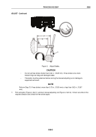
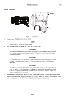
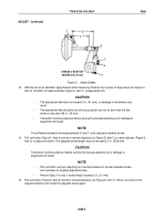
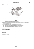
Cage brake chamber (Figure 1, Item 1) (TM 9-2330-342-10) (WP
0190).
6
5
4
1
2
3
Figure 1.
Adjust Brakes.
2.
Pull out button (Figure 1, Item 6) from slack adjuster (Figure 1, Item 5).
3.
Turn manual adjusting nut (Figure 1, Item 4) counterclockwise until brake linings (Figure 1, Item 3) contact
brake drum (Figure 1, Item 2).
4.
Turn manual adjusting nut (Figure 1, Item 4) clockwise 1/2 turn.
TM 9-2330-342-23&P
0066
0066-1
Back to Top

