TM-9-2330-342-23-P - Page 597 of 1348
INSTALLATION - Continued
2.
Using lifting device and the aid of an assistant, position axle (Figure 8, Item 1) and support with jackstands.
NOTE
•
If replacing axle with new assembly, one side of the axle will have the adjustment
plate welded while the other will not. This unwelded plate will allow axle adjustment
and will be welded once alignment is completed. If installing the same axle, the
adjustment plates will already be welded on each side. Alignment procedures will be
necessary if installing a new axle. If installing the same axle, alignment only needs
to be verified.
•
Steps (3) and (4) apply to side of axle that has adjustment plate welded.
3.
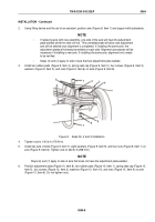
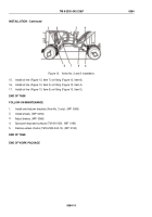
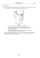
Install two rubber pads (Figure 9, Item 4), spring seat cap (Figure 9, Item 3), four screws (Figure 9, Item 2),
washers (Figure 9, Item 5), and nuts (Figure 9, Item 6) on axle (Figure 9, Item 8).
1
8
9
1
2
3
4
5
6
7
Figure 9.
Axles No. 2 and 3 Installation.
4.
Tighten nuts to 130 lb-ft (176 N·m).
5.
Install two axle U-bolts (Figure 9, Item 7), eight washers (Figure 9, Item 9), and four nuts (Figure 9, Item 1) on
axle (Figure 9, Item 8). Tighten nuts to 220 lb-ft (298 N·m).
NOTE
Steps (6) and (7) apply to side of axle that does not have the adjustment plate welded.
6.
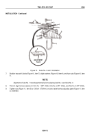
Position adjustment plate (Figure 10, Item 8), two rubber pads (Figure 10, Item 1), spring seat cap (Figure 10,
Item 5), four screws (Figure 10, Item 2), washers (Figure 10, Item 10), and nuts (Figure 10, Item 9) on axle
(Figure 10, Item 6). Do not tighten nuts.
TM 9-2330-342-23&P
0064
0064-9
Back to Top

