TM-9-2330-342-23-P - Page 606 of 1348
ADJUST - Continued
5.
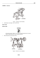
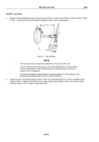
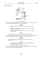
Measure distance between center of large clevis pin (Figure 2, Item 2) and bottom of brake chamber (Figure
2, Item 1), (measurement A) with brake in released position. Record measurement.
A
2
1
Figure 2.
Adjust Brakes.
NOTE
•
The free stroke sets the clearance between the linings and brake drum.
•
If, when checking free stroke as part of Preventive Maintenance, the free stroke is
not within specifications, refer to Brake System Troubleshooting to correct the
problem prior to proceeding.
•
The difference between measurement B and measurement A is the free stroke. Free
stroke must be between 0.62 to 0.75 in. (15.87-19.05 mm).
6.
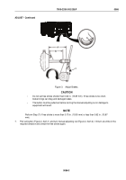
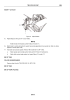
Using a pry bar, move slack adjuster (Figure 3, Item 3) so that linings (Figure 3, Item 2) are against drum
(Figure 3, Item 1). Measure the distance from center of large clevis (Figure 2, Item 2) to bottom of brake
chamber (Figure 2, Item 1) again, (measurement B).
TM 9-2330-342-23&P
0066
0066-2
Back to Top

