TM-9-2330-342-23-P - Page 724 of 1348
INSTALLATION - Continued
6
7
8
1
2
4
5
3
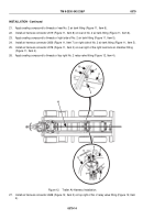
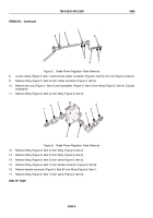
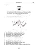
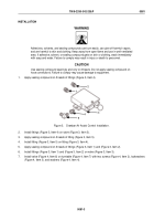
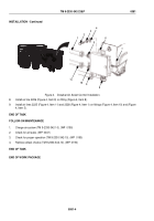
Figure 8.
Brake Power Regulator Valve Installation.
15.
Install fitting (Figure 8, Item 4) on rubber connector (Figure 8, Item 5).
16.
Install rubber connector (Figure 8, Item 5) on rod (Figure 8, Item 8) and tighten clamp (Figure 8, Item 1).
17.
Apply soap solution to rod (Figure 8, Item 8) and rubber connector (Figure 8, Item 7).
18.
Install rod (Figure 8, Item 8) on rubber connector (Figure 8, Item 7) and tighten clamp (Figure 8, Item 6).
CAUTION
Ensure linkage faces away from frame or damage to equipment may result.
19.
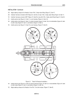
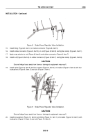
Install valve (Figure 9, Item 5) and four screws (Figure 9, Item 4) on bracket (Figure 9, Item 3) with four
lockwashers (Figure 9, Item 2) and nuts (Figure 9, Item 1).
1
2
3
4
5
Figure 9.
Brake Power Regulator Valve Installation.
CAUTION
Ensure linkage faces away from frame or damage to equipment may result.
20.
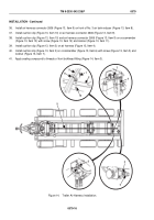
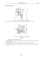
Install two washers (Figure 10, Item 4) and fitting (Figure 10, Item 1) on bracket (Figure 10, Item 5) with
lockwasher (Figure 10, Item 3) and nut (Figure 10, Item 2).
TM 9-2330-342-23&P
0080
0080-6
Back to Top

