TM-9-2330-342-23-P - Page 717 of 1348
INSTALLATION - Continued
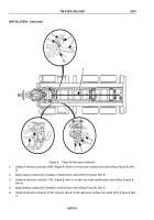
42.
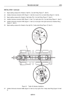
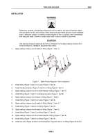
Install air harness connector 2143 (Figure 14, Item 4) on front bulkhead fitting (Figure 14, Item 3).
43.
Install air harness connector 2637 (Figure 14, Item 8) on top of No. 3 relay valve fitting (Figure 14, Item 7).
44.
Install air harness connector 2078 (Figure 14, Item 6) on right side of load lock control valve fitting (Figure 14,
Item 5).
45.
Install cushion clip (Figure 14, Item 11) on air harness (Figure 14, Item 9).
46.
Install cushion clip (Figure 14, Item 11) and air harness (Figure 14, Item 9) on crossmember (Figure 14, Item
2) with screw (Figure 14, Item 1) and locknut (Figure 14, Item 10).
END OF TASK
FOLLOW-ON MAINTENANCE
1.
Charge air system (TM 9-2330-342-10). (WP
0190)
2.
Check for air leaks. (WP
0047)
3.
Remove wheel chocks (TM 9-2330-342-10). (WP
0190)
END OF TASK
END OF WORK PACKAGE
TM 9-2330-342-23&P
0079
0079-17/18 blank
Back to Top

