TM-9-2330-342-23-P - Page 747 of 1348
FIELD MAINTENANCE
INVERSION VALVE REPLACEMENT
INITIAL SETUP:
Tools and Special Tools
Cap and Plug Set (WP
0194, Table 1, Item 4)
Tool Kit, General Mechanic's: Automotive
(WP
0194, Table 1, Item 47)
Materials/Parts
Sealing Compound (WP
0193, Table 1, Item 53,
54)
Tags, Identification (WP
0193, Table 1, Item 59)
Lockwasher Qty:
2 (WP
0195, Table 1, Item 78)
References
Fig. 25 (WP
0160)
WP
0047
Equipment Condition
Wheels chocked (TM 9-2330-342-10). (WP
0190)
Drawbar lowered (TM 9-2330-342-10).
(WP
0190)
Air system drained (TM 9-2330-342-10).
(WP
0190)
REMOVAL
CAUTION
Equipment may be damaged by foreign matter if hoses, tubes, and connectors are not
plugged and capped when removed.
NOTE
•
Tag all air lines prior to removal.
•
Cap and plug all air lines and connectors after removal.
1.
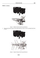
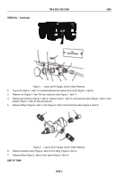
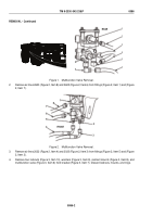
Remove air lines 2224 (Figure 1, Item 6), 2226 (Figure 1, Item 9), and 2223 (Figure 1, Item 11) from fittings
(Figure 1, Item 13), (Figure 1, Item 10), and (Figure 1, Item 8).
1
2
3
4
5
6
7
8
9
10
11
12
13
Figure 1.
Inversion Valve Removal.
2.
Remove air lines 2225 (Figure 1, Item 5) and 2231 (Figure 1, Item 1) from fitting (Figure 1, Item 3).
TM 9-2330-342-23&P
0084
0084-1
Back to Top

