TM-9-2330-342-23-P - Page 754 of 1348
INSTALLATION - Continued
1
2
3
4
5
6
7
8
9
10
11
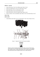
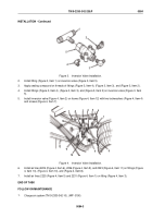
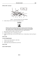
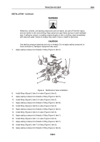
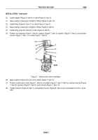
Figure 4.
Load Lock Air Supply Control Valve Installation.
10.
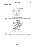
Install nut (Figure 4, Item 10) on load lock valve (Figure 4, Item 7).
WARNING
Adhesives, solvents, and sealing compounds can burn easily, can give off harmful vapors,
and are harmful to skin and clothing. Keep away from open flame and use in well-ventilated
area. If adhesive, solvent, or sealing compound gets on skin or clothing, wash immediately
with soap and water. Failure to comply may result in injury or death to personnel.
11.
Apply sealing compound to threads of shaft (Figure 4, Item 9).
12.
Install knob (Figure 4, Item 11) on shaft (Figure 4, Item 9).
13.
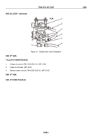
Install air lines 2080 (Figure 4, Item 6) and 2078 (Figure 4, Item 1) on fittings (Figure 4, Item 5) and (Figure 4,
Item 2).
END OF TASK
FOLLOW-ON MAINTENANCE
1.
Charge air system (TM 9-2330-342-10). (WP
0190)
2.
Check for air leaks. (WP
0047)
3.
Remove wheel chocks (TM 9-2330-342-10). (WP
0190)
END OF TASK
END OF WORK PACKAGE
TM 9-2330-342-23&P
0085
0085-4
Back to Top

