TM-9-2330-342-23-P - Page 749 of 1348
INSTALLATION - Continued
1
2
3
4
5
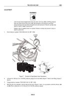
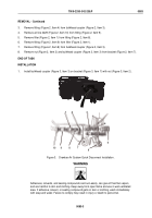
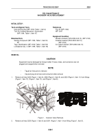
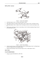
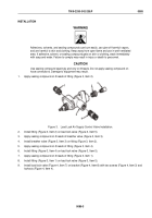
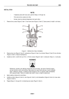
Figure 3.
Inversion Valve Installation.
2.
Install fitting (Figure 3, Item 1) on inversion valve (Figure 3, Item 5).
3.
Apply sealing compound on threads of fittings (Figure 3, Item 4), (Figure 3, Item 3), and (Figure 3, Item 2).
4.
Install fittings (Figure 3, Item 4), (Figure 3, Item 3), and (Figure 3, Item 2) on inversion valve (Figure 3, Item
5).
5.
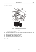
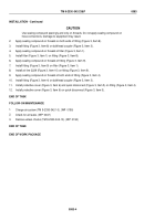
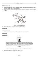
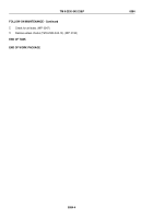
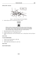
Install inversion valve (Figure 4, Item 2) on frame (Figure 4, Item 12) with two lockwashers (Figure 4, Item 4)
and screws (Figure 4, Item 7).
1
2
3
4
5
6
7
8
9
10
11
12
13
Figure 4.
Inversion Valve Installation.
6.
Install air lines 2224 (Figure 4, Item 6), 2226 (Figure 4, Item 9), and 2223 (Figure 4, Item 11) on fittings (Figure
4, Item 13), (Figure 4, Item 10), and (Figure 4, Item 8).
7.
Install air lines 2225 (Figure 4, Item 5) and 2231 (Figure 4, Item 1) on fitting (Figure 4, Item 3).
END OF TASK
FOLLOW-ON MAINTENANCE
1.
Charge air system (TM 9-2330-342-10). (WP
0190)
TM 9-2330-342-23&P
0084
0084-3
Back to Top

