TM-9-2330-342-23-P - Page 867 of 1348
INSTALLATION - Continued
1
2
3
4
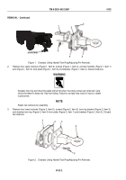
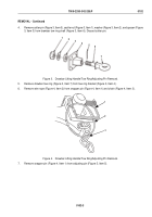
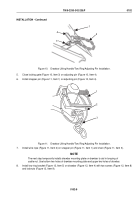
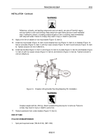
Figure 10.
Drawbar Lifting Handle/Tow Ring/Adjusting Pin Installation.
5.
Close locking gate (Figure 10, Item 3) on adjusting pin (Figure 10, Item 4).
6.
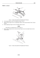
Install snapper pin (Figure 11, Item 1) on adjusting pin (Figure 10, Item 4).
1
2
3
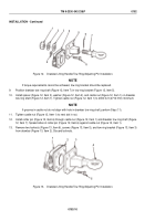
Figure 11.
Drawbar Lifting Handle/Tow Ring/Adjusting Pin Installation.
7.
Install wire rope (Figure 11, Item 2) on snapper pin (Figure 11, Item 1) and chain (Figure 11, Item 3).
NOTE
The next step temporarily installs drawbar mounting plate on drawbar to aid in torquing of
castle nut. Use bottom two holes of drawbar mounting plate and upper two holes of drawbar.
8.
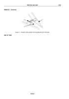
Install tow ring bracket (Figure 12, Item 5) on drawbar (Figure 12, Item 4) with two screws (Figure 12, Item 8)
and locknuts (Figure 12, Item 9).
TM 9-2330-342-23&P
0102
0102-9
Back to Top

