TM-9-2330-342-23-P - Page 875 of 1348
DISASSEMBLY - Continued
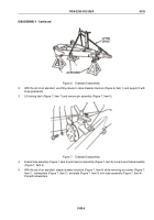
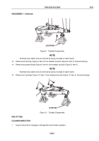
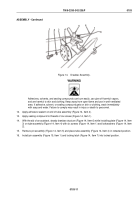
LIFTING
DEVICE
1
JACKSTANDS
Figure 6.
Drawbar Disassembly.
2.
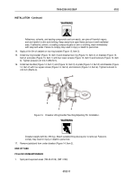
With the aid of an assistant, use lifting device to raise drawbar structure (Figure 6, Item 1) and support it with
three jackstands.
3.
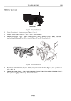
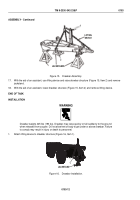
Lift locking latch (Figure 7, Item 7) and remove pin assembly (Figure 7, Item 5).
1
2
3
4
5
6
7
Figure 7.
Drawbar Disassembly.
4.
Extend tube assembly (Figure 7, Item 4) and insert pin assembly (Figure 7, Item 5) in rear hole of tube assembly
(Figure 7, Item 4).
5.
With the aid of an assistant, steady drawbar structure (Figure 7, Item 6) while removing six screws (Figure 7,
Item 1), lockwashers (Figure 7, Item 2), and plate (Figure 7, Item 3) from tube assembly (Figure 7, Item 4).
Discard lockwashers.
TM 9-2330-342-23&P
0103
0103-5
Back to Top

