TM-9-2330-342-23-P - Page 880 of 1348
ASSEMBLY - Continued
4.
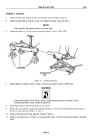
Install two wiper seals (Figure 12, Item 2) in drawbar structure (Figure 12, Item 1).
5.
Install two grease fittings (Figure 12, Item 4) on drawbar structure (Figure 12, Item 1).
NOTE
If tube assembly was replaced, perform next two steps.
6.
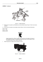
Install plate (Figure 13, Item 3) on tube assembly (Figure 13, Item 2) (WP
0102).
JACKSTANDS
TRANSMISSION
JACK
1
2
3
4
5
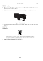
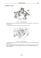
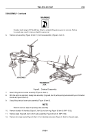
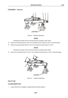
Figure 13.
Drawbar Assembly.
7.
Install drawbar lift handles (Figure 13, Item 4) and tow ring (Figure 13, Item 5) (WP
0102).
WARNING
Drawbar shaft weighs 187 lbs (85 kg). Attach a suitable lifting device prior to removal. Failure
to comply may result in injury or death to personnel.
8.
Attach lifting device to tube assembly (Figure 13, Item 2).
9.
With the aid of an assistant, steady tube assembly (Figure 13, Item 2) and install tube assembly (Figure 13,
Item 2) in drawbar structure (Figure 13, Item 1).
10.
Remove lifting device from tube assembly (Figure 13, Item 2).
11.
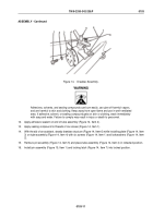
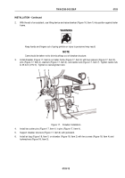
Install pin assembly (Figure 14, Item 5) in tube assembly (Figure 14, Item 4) with tube assembly in extended
mode.
TM 9-2330-342-23&P
0103
0103-10
Back to Top

