TM-9-2330-342-23-P - Page 877 of 1348
DISASSEMBLY - Continued
JACKSTANDS
4
1
2
3
2
1
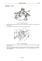
Figure 9.
Drawbar Disassembly.
NOTE
Bushings have seams and are removed by prying one edge of seam inward.
13.
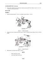
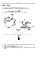
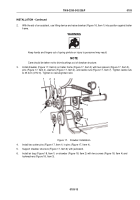
Remove two bushings (Figure 9, Item 2) from drawbar structure (Figure 9, Item 3). Discard bushings.
14.
Remove two grease fittings (Figure 9, Item 4) from drawbar structure (Figure 9, Item 3).
NOTE
Bushings have seams and are removed by prying one edge of seam inward.
15.
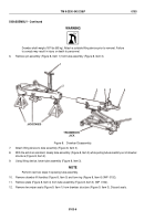
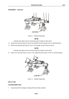
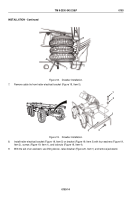
Remove four bushings (Figure 10, Item 1) from drawbar structure (Figure 10, Item 2). Discard bushings.
1
1
JACKSTAND
2
Figure 10.
Drawbar Disassembly.
END OF TASK
CLEANING/INSPECTION
1.
Inspect tube shaft for warpage or damage that would impair operation.
TM 9-2330-342-23&P
0103
0103-7
Back to Top

