TM-9-2330-342-23-P - Page 868 of 1348
INSTALLATION - Continued
1
2
3
4
5
6
7
8
9
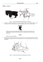
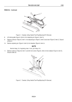
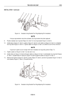
Figure 12.
Drawbar Lifting Handle/Tow Ring/Adjusting Pin Installation.
NOTE
If torque requirements cannot be achieved, tow ring bracket should be replaced.
9.
Position drawbar tow ring shaft (Figure 12, Item 7) in tow ring bracket (Figure 12, Item 5).
10.
Install spacer (Figure 12, Item 3), washer (Figure 12, Item 2), and castle nut (Figure 12, Item 1) on drawbar
tow ring shaft (Figure 12, Item 7). Tighten castle nut (Figure 12, Item 1) to 2000 lb-ft (2712 N·m) minimum.
NOTE
If grooves in castle nut do not align with hole in drawbar tow ring shaft, perform Step (11).
11.
Tighten castle nut (Figure 12, Item 1) to next slot in nut.
12.
Install cotter pin (Figure 12, Item 6) through castle nut (Figure 12, Item 1) and drawbar tow ring shaft (Figure
12, Item 7). Spread sides of cotter pin (Figure 12, Item 6) against castle nut (Figure 12, Item 1).
13.
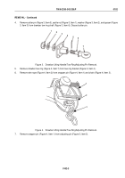
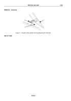
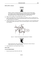
Remove two locknuts (Figure 13, Item 6), screws (Figure 13, Item 5), and tow ring bracket (Figure 13, Item 3)
from drawbar (Figure 13, Item 2). Discard locknuts.
6
1
2
3
4
5
Figure 13.
Drawbar Lifting Handle/Tow Ring/Adjusting Pin Installation.
TM 9-2330-342-23&P
0102
0102-10
Back to Top

