TM-9-2330-342-23-P - Page 894 of 1348
INSTALLATION - Continued
FRONT
1
2
3
4
5
6
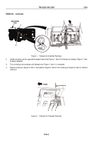
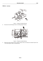
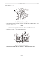
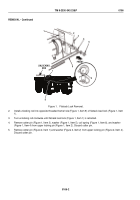
Figure 11.
Flatrack Air Chamber Installation.
9.
Install locking pin (Figure 11, Item 2) through load lock (Figure 11, Item 3) and clevis (Figure 11, Item 1).
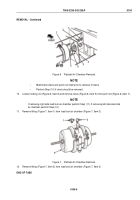
10.
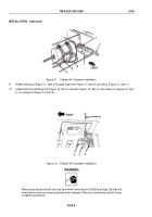
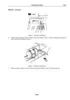
Install load lock indicating rod (Figure 12, Item 3), washer (Figure 12, Item 2), and cotter pin (Figure 12, Item
1) on locking pin (Figure 12, Item 4).
FRONT
1
2
3
4
Figure 12.
Flatrack Air Chamber Installation.
WARNING
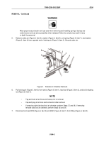
Wear proper eye protection and use care when removing and installing springs. Springs are
under tension and can act as projectiles when released. Failure to comply may result in injury
or death to personnel.
TM 9-2330-342-23&P
0104
0104-8
Back to Top

