TM-9-2330-342-23-P - Page 955 of 1348
FIELD MAINTENANCE
TIE DOWN SUPPORT TUBE REPLACEMENT
INITIAL SETUP:
Tools and Special Tools
Goggles, Industrial (WP
0194, Table 1, Item 47)
Handle, Ratchet, 3/4" Drive, 17" Long (WP
0194,
Table 1, Item 42)
Respirator, Air Filter (WP
0194, Table 1, Item 33)
Sander/Grinder, 4-1/2" (WP
0194, Table 1, Item
42)
Socket, Socket Wrench, 3/4" Drive, 12 Pt, 1-5/16"
(WP
0194, Table 1, Item 42)
Tool Kit, General Mechanic’s: Automotive
(WP
0194, Table 1, Item 47)
Wrench, Combination, 1-5/16" (WP
0194, Table 1,
Item 42)
Wrench, Pipe, 36" (WP
0194, Table 1, Item 42)
Wrench, Torque, Click, Ratcheting, 3/4" Drive, 600
ft-lb (WP
0194, Table 1, Item 42)
Materials/Parts
Compound, Sealing
(WP
0193, Table 1, Item 29, 30, 31)
Personnel Required
Wheeled Vehicle Mechanic (2)
References
Fig. 29 (WP
0164)
Equipment Condition
Wheels chocked (TM 9-2330-342-10). (WP
0190)
REMOVAL
NOTE
•
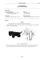
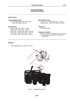
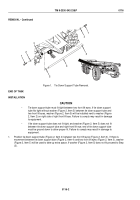
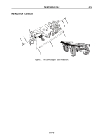
Tie down support tube assembly requires a total of four washers. Washer (Figure 1,
Item 5) may be positioned between tie down support tube and right front lift eye or
combined with washer (Figure 1, Item 2) on right side of right front lift eye.
•
Note position of washers prior to removal to ensure proper installation.
With the aid of an assistant, remove two screws (Figure 1, Item 1), three washers (Figure 1, Item 2), washer
(Figure 1, Item 5), and tie down support tube (Figure 1, Item 4) from two front lift eyes (Figure 1, Item 3).
TM 9-2330-342-23&P
0116
0116-1
Back to Top

