TM-9-2330-342-23-P - Page 956 of 1348
REMOVAL - Continued
1
1
2
5
2
2
4
3
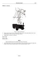
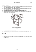
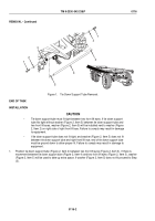
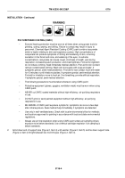
Figure 1.
Tie Down Support Tube Removal.
END OF TASK
INSTALLATION
CAUTION
•
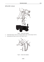
Tie down support tube must fit tight between two front lift eyes. If tie down support
tube fits tight without washer (Figure 2, Item 5) between tie down support tube and
two front lift eyes, washer (Figure 2, Item 5) will be installed next to washer (Figure
2, Item 2) on right side of right front lift eye. Failure to comply may result in damage
to equipment.
•
If tie down support tube does not fit tight, and washer (Figure 2, Item 5) does not fit
between tie down support tube and right front lift eye, end of tie down support tube
must be ground down to allow proper fit. Failure to comply may result in damage to
equipment.
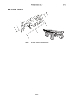
1.
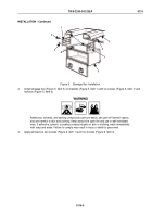
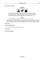
Position tie down support tube (Figure 2, Item 4) between two front lift eyes (Figure 2, Item 3). If there is
movement between tie down support tube (Figure 2, Item 4) and two front lift eyes (Figure 2, Item 3), washer
(Figure 2, Item 5) will be used to take up extra space. If washer (Figure 2, Item 5) does not fit proceed to Step
(2).
TM 9-2330-342-23&P
0116
0116-2
Back to Top

