TM-9-2350-238-20-1 - Page 590 of 1364
TM 9-2350-238-20-1
2-71. MAINTENANCE OF NEUTRAL POSITION SWITCH AND RELATED PARTS (CONT).
1
Inspect for broken, damaged, or missing parts.
2
If damaged or missing, replace marker bands. Etch or stamp lead number on new band.
3
For repair of electrical shell connectors, refer to general maintenance, page 2-371.
4
Repair is by replacement of authorized parts (TM 9-2350-238-24P-1).
1
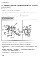
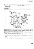
Install mounting nut (1) and key washer (2) on neutral position sensitive switch (3).
2
Insert neutral position sensitive switch (3) through mounting hole in bracket (4).
3
Install Iockwasher (5), adjusting nut (6), and roller guide (7) on neutral position sensitive switch
(3).
4
Install two sleeve spacers (8) and bracket (4) to mounting surface. Secure with two flat
washers (9) and two hexagon capscrews (10).
5
Install loop clamp (11) and assembled washer bolt (12).
2-564
Back to Top

