TM-9-2350-238-20-1 - Page 858 of 1364
TM 9-2350-238-20-1
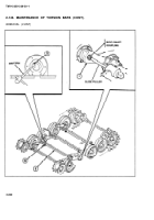
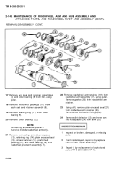
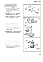
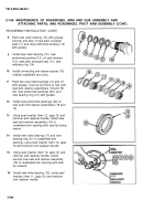
2-143. MAINTENANCE OF TORSION BARS
1
2
3
4
5
6
7
8
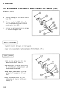
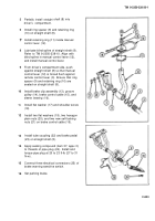
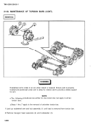
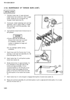
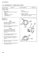
If broken torsion bar (1) was removed,
install torsion bar socket (2), refer to page
2-834. Install but do not tighten four
hexagon head capscrews (3).
If removed, install roadwheel arm and hub
assembly, refer to page 2-836; or install
idler wheel arm and hub assembly, refer
to page 2-855.
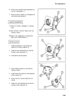
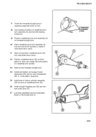
Coat splines at each end of torsion bar (1)
with grease.
●
Torsion bars are not identical.
Ensure that torsion bar is correct
for installation position. Part
number is stamped on large end
of torsion bar.
●
Do not damage splines during
installation.
Insert inner end (4) of torsion bar (1) into
opening in arm and hub assembly (5). Be
sure blind spline (6) is up.
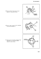
Insert torsion bar (1) until spline touches
torsion bar socket (2).
Rotate torsion bar (1) approximately 1/4
turn clockwise on the right side of the
vehicle and approximately 1/4 turn
counterclockwise on the left side of the
vehicle to align and engage the blind
spline on the end of the torsion bar with
the blind spline in the torsion bar socket
(2).
(CONT).
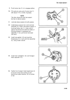
Insert torsion bar (1) only enough to engage blind spline of torsion bar socket (2).
Raise arm and hub assembly (5) until blind spline in arm is aligned with blind spline (7) on outer
end (8) of torsion bar (1).
2-832
Back to Top

