TM-9-2350-238-20-1 - Page 862 of 1364
TM 9-2350-238-20-1
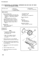
2-145. MAINTENANCE OF ROADWHEEL ARM AND HUB ASSEMBLY AND
ATTACHING PARTS; AND ROADWHEEL PIVOT ARM ASSEMBLY.
This task covers:
a.
Removal/Disassembly
c. Reassembly/Installation
b.
Inspection/Repa\r
INITIAL SETUP
Tools and Special Tools
Automotive maintenance and repair shop
equipment: organizational maintenance,
common no. 1 (less power) (item 80,
appx B)
●
Mechanical puller kit
Hexagon head capscrew (3) (item 23,
appx G)
Hub spacer replacer (item 19, appx G)
Puller adapter (item 2, appx G)
Remover and replacer handle (item 9,
appx G)
Seal guard replacer (item 21, appx G)
Seal inserter (item 11, appx G)
Seal inserter (item 12, appx G)
Slide puller (item 18, appx G)
Sling (item 82, appx B)
Threaded straight pin (2) (item 17, appx G)
Materials/Parts
Bearing ring
Connecting arm sleeve spacer
Cotter pin (2)
Gasket
Grease (item 20, appx
Lockwasher (6)
Plain encased seal
Plain encased seal
Preformed packing
Preformed packing (2)
Roller bearing
Roller bearing (2)
c)
Seal and retainer assembly (2)
Sealing compound (item 37, appx C)
Personnel Required
Two
References
TM 9-2350-238-10
TM 9-2350-238-24P-1
Equipment Conditions
2-848 RoadWheel removed
2-827 Torsion bar removed
2-842 Roadwheel suspension hub
removed
1
2
3
4
NOTE
Procedures are written for one road-
wheel arm and hub assembly but
apply to all roadwheel arm and hub
assemblies.
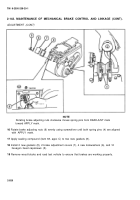
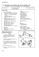
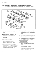
Remove six hexagon head capscrews (1)
and six Iockwashers (2).
Refer to page 2-831 to gain access to
lock-out cylinder assembly (3) connected
to roadwheel pivot arm assembly being
removed.
Remove two cotter pins (4).
Rig a sling to support lockout cylinder
assembly (3).
2-836
Back to Top

