TM-9-2350-238-20-1 - Page 871 of 1364
TM 9-2350-238-20-1
1
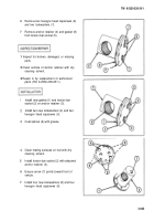
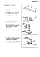
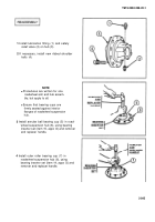
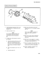
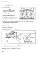
Install lubrication fitting (1) and safety
relief valve (2) on hub (3).
2
If necessary, install new ribbed shoulder
bolts (4).
NOTE
●
Procedures are written for one
roadwheel arm and hub assem-
bly, but apply to all.
●
Ensure that bearing cups are
firmly seated against interior
flanges of roadwheel suspension
hub.
3
Install annular ball bearing cup (5) in road-
wheel suspension hub (6), using bearing
inserter set (item 15, appx G) and remover
and replacer handle.
4
Install outer roller bearing cup (7) in
roadwheel suspension hub (6), using
bearing inserter set (item 14, appx G) and
remover and replacer handle.
2-845
Back to Top

