TM-9-2350-238-20-1 - Page 873 of 1364
TM 9-2350-238-20-1
1
2
3
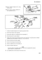
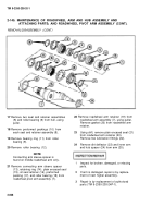
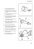
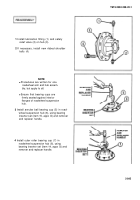
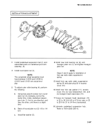
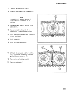
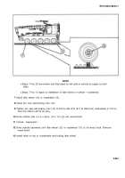
Install roadwheel suspension hub (1) and
assembled parts on roadwheel pivot arm
assembly (2).
Install round plain nut (3).
NOTE
The completed wheel assembly must
have between 0.0005 and 0.0050 in.
(0.0013 and 0.0130 cm) actual end
play.
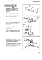
To adjust outer roller bearing (4), perform
the following.
a.
b.
c.
4
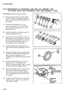
Install new lock bearing nut (6) and
hexagon plain nut (7), and tighten hexagon
plain nut.
NOTE
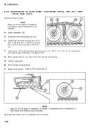
Steps 5 and 6 apply to installation of
hub cap radio static suppression
spring.
5
Install hub cap radio static suppression
spring (8) and pipe plug (9) in access
cover (10).
6
Install new hub cap gasket (11), access
cover (10), six new Iockwashers (12), and
Using face wrench socket, turn round
six hexagon head capscrews (13).
plain nut (3) clockwise, and at the
same time, rotate roadwheel suspen-
7
Torque six hexagon head capscrews (13)
sion hub (1), first in one direction, and
to 32 to 35 ft-lb (43 to 47 N-m) (dry) or 23
then the other, until there is a slight
to 25 ft-lb (31 to 34 N-m) (lubricated).
bind.
8
Lubricate roadwheel suspension hub.
Back off round plain nut (3) 1/6 to 1/4
Refer to TM 9-2350-238-10.
turn.
Install flat washer (5).
2-847
Back to Top

