TM-9-2350-238-20-1 - Page 859 of 1364
TM 9-2350-238-20-1
9
10
11
12
13
14
15
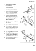
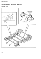
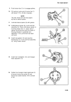
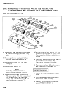
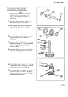
Push torsion bar (1) in to engage splines.
Fill cavity at outer end of torsion bar (1)
with about 1/4 in. (6 mm) of grease.
NOTE
The idler wheel arm and hub assem-
bly has no sleeve spacer.
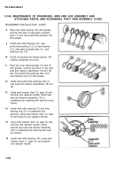
Lubricate sleeve spacer (9) with grease.
Install sleeve spacer (9) in arm and hub
assembly (5). Press until sleeve spacer is
touching torsion bar (1). Outer end of
spacer should be even with the inside of
the plug threads in roadwheel arm
assembly. If not, pull torsion bar back
until even.
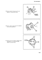
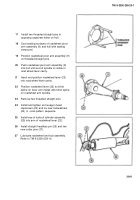
Install new gasket (10) and machine
thread plug (11) in arm and hub assembly
(5), using socket wrench.
Install new Iockwasher (12) and hexagon
head capscrew (13).
Tighten four hexagon head capscrews (3)
to secure torsion bar socket (2) and
torsion bar socket retainer (14) to bottom
of hull.
2-833
Back to Top

