TM-9-2350-238-20-1 - Page 910 of 1364
TM 8-2350-238-20-1
2-155. MAINTENANCE OF LOCKOUT CYLINDER AND RELATED PARTS (CONT).
●
●
●
●
●
●
NOTE
The following procedures are written for one lockout cylinder, but apply to all
lockout cylinders.
For right side number 1 and number 2 lockout cylinders, gain access through
right side of powerplant compartment.
For right side number 3 and number 4 lockout cylinders, gain access through
bottom right front of turret well.
For left side number 1 and number 2 lockout cylinders, gain access through
bottom rear of drivets compartment.
For left side number 3 lockout cylinder,
turret well.
For left side number 4 lockout cylinder,
turret well.
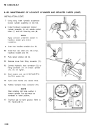
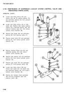
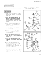
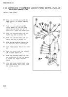
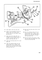
1
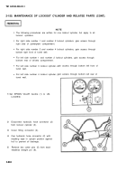
Set SPNSN VALVE handle (1) to UN-
LOCKED.
2
3
4
5
Disconnect hydraulic hose connector (2)
from lockout cylinder (3).
Cover fitting connector (4).
Cap hydraulic hose connector (2) with
masking tape in upright position against
hull to prevent oil drainage.
Remove two cotter pins (5) from each
headless straight pin (6).
2-884
gain access through bottom left front of
gain access through bottom left rear of
Back to Top

